Regulated Three-Stage (R3S) Turbocharging System – Two-Stage Exhaust Gas Turbocharging
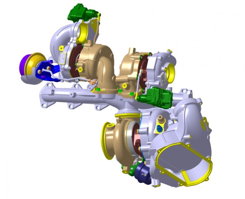
BorgWarner engineered the R3S turbocharging system which consists of two small high-pressure VTG turbochargers integrated with one larger low-pressure turbocharger.
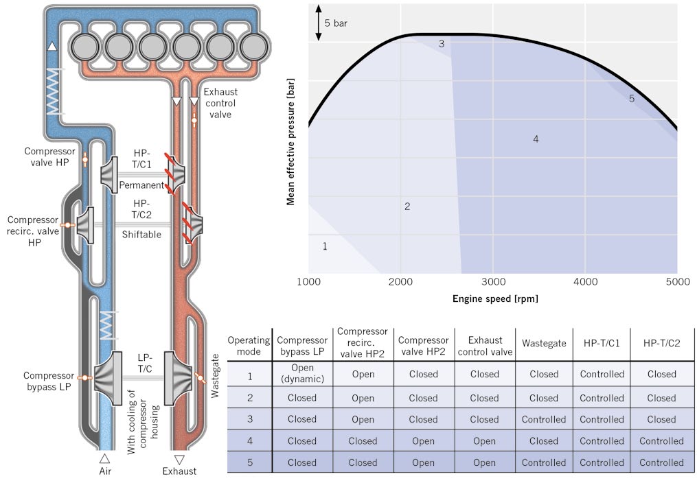
BorgWarner’s regulated three-stage (R3S) turbocharging system combines the benefits of two-stage turbocharging for high specific power output and parallel sequential turbocharging for best drivability. The innovative technology increases power density while improving fuel economy and reducing emissions for downsized diesel engines.
Two-stage turbocharging system with three exhaust turbochargers (parallel sequential high pressure turbos in series with a low pressure stage turbo) (Source: ATZ)
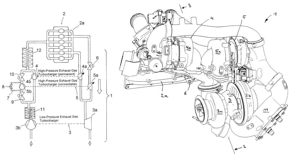
The fresh combustion air is taken in by the two-stage exhaust gas turbocharging arrangement 1, again shown by a small arrow at an inlet opening of the intake system. The combustion air first flows through a low-pressure compressor housing 3 b of the low-pressure exhaust gas turbocharger 3, is subsequently cooled down in a first charge air cooler 11 and is subsequently distributed to two separate gas-bearing branches. Thus, the combustion air is permanently conveyed through a high-pressure compressor housing 4 b of the high-pressure exhaust gas turbocharger 4 and is subsequently cooled by a second charge air cooler 12, which again cools the recompressed and thereby heated combustion air. Subsequently, the combustion air is conveyed into the cylinders of the internal-combustion engine 2 (indicated by ovals).
The first and the second charge air coolers 11, 12 are used for the intermediate cooling. The second and the third throttling elements 9 and 10, respectively, are situated at the input side and the output side of the second high-pressure compressor housing 5 b, which can be connected and disconnected. The second and the third throttling elements 9 and 10 are general valves for the shut-off as well as a bypass pipe. The bypass 7 connects the inlet of the second high-pressure compressor housing 5 b with the outlet of the second high-pressure compressor housing 5 b also in a connectable manner. On the exhaust gas side, a shut-off valve, i.e., a fourth throttling element 6, is situated in front of the inlet of the therefore connectable and disconnectable second high-pressure turbine housing 5 a in order to separate it from the exhaust gas flow. (Source: Bayerische Motoren Werke Aktiengesellschaft)